- 您现在的位置:买卖IC网 > Sheet目录1990 > BH2226FV-FE2 (Rohm Semiconductor)IC DAC 8BIT 8-CHAN SSOP-B16
BH2226FV,BH2226F
Technical Note
5/9
www.rohm.com
2009.07 - Rev.B
2009 ROHM Co., Ltd. All rights reserved.
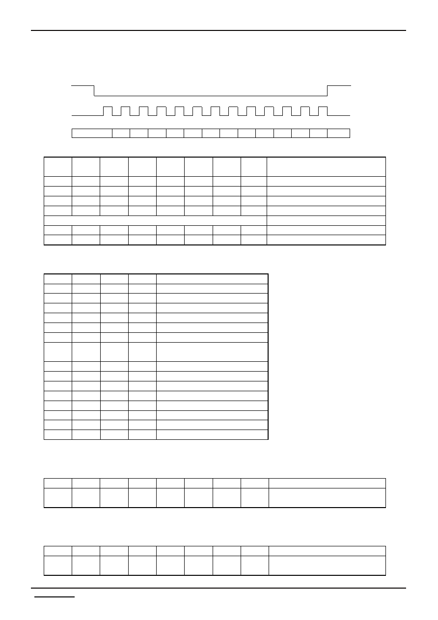
●Operation Description
·Command Transmission
The Control command consists of 3 lines of 12bit serial input data (MSB first).
DI data is read at the rising edge of the CLK, and becomes valid in the CSB Low area (before the CSB rise for 12bit data).
Fig.4
Data Settings
D0
D1
D2
D3
D4
D5
D6
D7
Setting
0
At D/A setting:GND
1
0
At D/A setting:(VCC-GND)/256x1
0
1
0
At D/A setting:(VCC-GND)/256 x 2
1
0
At D/A setting:(VCC-GND)/256 x 3
0
1
0
At D/A setting:(VCC-GND)/256 x 4
~
0
1
At D/A setting:(VCC-GND)/256 x 254
1
At D/A setting:(VCC-GND)/256 x 255
(Note)
Default
D[7:0]=00h
Channel Settings
D8
D9
D10
D11
Setting
0
Power down setting (default)
0
1
DA1
0
1
0
DA2
0
1
DA3
0
1
0
DA4
0
1
0
1
DA5
0
1
0
DA6
0
1
DA7
1
0
DA8
1
0
1
Power down release
1
0
1
0
Inconsequential
1
0
1
Inconsequential
1
0
I/O D/A select
1
0
1
I/O serialParallel
1
0
I/O parallelSerial
1
I/O status setting
Input / Output D/A Selection settings :Each channel can be set for either I/O port or D/A converter output.
0: I/O mode (When I/O mode is selected, set the status as well.)
1: D/A mode (Set the I/O status to output mode.)
D0
D1
D2
D3
D4
D5
D6
D7
Description
DA1
DA2
DA3
DA4
DA5
DA6
DA7
DA8
Corresponding terminals for I/O or
D/A selection
I/O Status Setting : Set the status of the I/O input output terminal by D0 ~ D7.
0: input mode (High-Z status)
1: output mode
D0
D1
D2
D3
D4
D5
D6
D7
Description
DA1
DA2
DA3
DA4
DA5
DA6
DA7
DA8
Corresponding terminals for status
setting
D0
D1
D2
D3
D4
D5
D6
D7
D8
D9
D10
D11
X
1
2
3
4
6
7
8
10
11
12
CSB
CLK
DI
9
5
发布紧急采购,3分钟左右您将得到回复。
相关PDF资料
BH2228FV-E2
IC DAC 8BIT 6-CHAN SSOP-B14
BQ4285EP
IC RTC W/114X8 NVSRAM 24-DIP
BQ4847YMT
IC RTC W/NVSRAM CONTROL T-MOD
BU2280FV-E2
IC CLOCK GEN DVD-VIDEO SSOP-B24
BU2363FV-E2
IC CLOCK GEN DVD-VIDEO SSOP-B16
BU2365FV-E2
IC CLOCK GEN W/VCXO SSOP-B24
BU2505FV-E2
IC DAC 10BIT 10-CHAN SSOP-B20
BU2508FV-E2
IC DAC 10BIT 4-CHAN SSOP14
相关代理商/技术参数
BH2226FV-F-E2
制造商:ROHM Semiconductor 功能描述:
BH2226GV-E2
制造商:ROHM Semiconductor 功能描述:
BH2227FV
制造商:ROHM 制造商全称:Rohm 功能描述:Standard 8bit 4ch-E6ch Type D/A Converters
BH2227FV_09
制造商:ROHM 制造商全称:Rohm 功能描述:Standard 8bit 4ch-E6ch Type D/A Converters
BH2227FV_11
制造商:ROHM 制造商全称:Rohm 功能描述:Standard 8bit 4ch?6ch Type D/A Converters
BH2227FV-E2
功能描述:数模转换器- DAC 8 BIT D/A CONVERTER 4 CHANNEL OUTPUT RoHS:否 制造商:Texas Instruments 转换器数量:1 DAC 输出端数量:1 转换速率:2 MSPs 分辨率:16 bit 接口类型:QSPI, SPI, Serial (3-Wire, Microwire) 稳定时间:1 us 最大工作温度:+ 85 C 安装风格:SMD/SMT 封装 / 箱体:SOIC-14 封装:Tube
BH2228FV
制造商:ROHM 制造商全称:Rohm 功能描述:Standard 8bit 4ch-E6ch Type D/A Converters
BH2228FV-E2
功能描述:数模转换器- DAC TUNING D/A CONVERTER RoHS:否 制造商:Texas Instruments 转换器数量:1 DAC 输出端数量:1 转换速率:2 MSPs 分辨率:16 bit 接口类型:QSPI, SPI, Serial (3-Wire, Microwire) 稳定时间:1 us 最大工作温度:+ 85 C 安装风格:SMD/SMT 封装 / 箱体:SOIC-14 封装:Tube